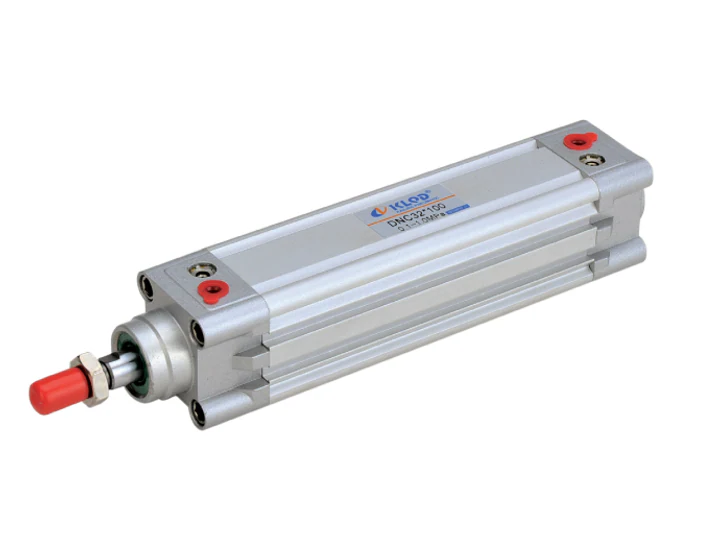
Why mounting, cushioning and stroke checks decide cylinder reliability
A pneumatic cylinder rarely fails alone. Misalignment, missed deceleration and unverified stroke positions transfer stress into the fluid control components, valves, fittings, guide rails and machine frame. For OEM machines, those errors usually appear as end-cap impact, rod seal wear, cycle drift, vibration, slow response or an unsafe stopping distance.
Ningbo Kailing Pneumatic Co., Ltd. specializes in fluid solenoid valves, pneumatic control valves and pneumatic actuators. Kailing has manufactured and exported pneumatic products since 2000. This guide is a specification and commissioning checklist for buyers, engineers and OEM integrators evaluating cylinder assemblies and related pneumatic components.
Start with the machine duty cycle
Before selecting hardware, document the application rather than only the bore and stroke:
- Load: moving mass, static load, off-center load and external forces.
- Motion: stroke length, stroke rate, travel speed, required dwell and end-position tolerance.
- Energy: available air pressure range, flow restriction and expected speed-control method.
- Environment: dust, washdown, vibration, temperature and contaminant exposure.
- Failure consequence: whether an overtravel event is merely inconvenient or creates a safety risk.
If the load has high inertia or the stop is safety-relevant, do not rely on standard cylinder cushioning alone. Confirm whether the machine requires an external stop, shock absorber, mechanical restraint or control-system interlock.
Choose the mounting style for load path, not convenience
The mounting should carry the load through the intended axis. A mounting style that is easy to install but allows side loading will shorten rod and seal life.
| Mounting style | Best suited to | Key check |
|---|---|---|
| Foot mount | Compact machines and straight-line loads | Confirm frame flatness and bolt pattern; avoid over-constraining thermal or assembly movement. |
| Front or rear flange | Short strokes where the cylinder body should be fixed close to the load | Check face alignment and bending stress on the flange and body. |
| Rear clevis | Loads that must swing through an arc | Confirm the pivot axis matches the machine’s motion path and cannot bind. |
| Trunnion | Long cylinders, conveyor and guided-load applications | Confirm bearing support, alignment and whether fixed/floating supports are required. |
| Guide-rod cylinder | Off-center loads or side-load-prone automation | Verify guide capacity, allowable side load and protected stroke positions. |
For OEM assembly, also confirm:
- rod thread, rod end accessory and available retraction clearance;
- port orientation and whether fittings interfere with nearby machine parts;
- hose or tube routing that avoids flexing and abrasion;
- torque values and thread-locking requirements from the machine design;
- whether the cylinder can be serviced without removing adjacent assemblies.
Set cushioning by speed, mass and stop tolerance
Cushioning is intended to reduce impact at end of stroke. It is not a substitute for correct load guidance or a complete machine safety system.
When selecting cushioning:
- Estimate moving mass and travel speed under the worst operating condition.
- Confirm whether adjustable or fixed cushioning is appropriate.
- Tune cushioning gradually from a conservative setting, not by repeatedly striking the end cap.
- Observe both extend and retract strokes; each direction may need a different setting.
- Check that speed-control valves, flow paths and exhaust restrictions do not make one stroke direction unstable.
- Verify that shorter cycle times do not create audible impact, bounce or drift.
Use an external shock absorber or mechanical stop when the moving mass exceeds the cylinder’s normal cushioning capability. For safety-relevant stopping, verify the complete machine design against the applicable local safety requirements and the machine maker’s instructions.
Verify stroke and end positions before release
A cylinder can be dimensionally correct and still misbehave in service. Commissioning should therefore check both commanded and physical positions.
Before power-up:
- confirm bore, stroke, retracted and extended dimensions against the approved drawing;
- check rod straightness, attachment alignment and port clearance;
- confirm sensors or switches have correct target positions and cannot be struck by the moving assembly;
- verify air preparation, pressure range and exhaust flow match the system design.
During powered trials:
- run at slow speed first, then increase to the specified cycle rate;
- check both stroke directions for smooth deceleration and no end-cap impact;
- record end-position repeatability where the machine requires it;
- check leakage at fittings, rod area and valve interfaces under normal pressure;
- confirm manual operation, fault recovery and emergency stop behavior according to the machine design.
Under production-like load:
- repeat the cycle with the real product, tooling and worst-case motion;
- inspect for hose stress, mounting movement, side-load marks or loosened fasteners;
- re-check cushioning and speed controls after warm-up and after any adjustment.
Buyer and OEM evaluation checklist
Use this checklist when comparing cylinder suppliers or preparing a machine package:
- Complete cylinder datasheet, dimensional drawing and CAD model.
- Mounting dimensions, thread details and installation notes.
- Pressure range, speed range and cushioning information applicable to the duty cycle.
- Rod-end and sensor options compatible with the machine controls.
- Seal and material compatibility for the operating environment.
- Required torque, adjustment and maintenance instructions.
- Test, inspection or acceptance criteria agreed before shipment.
FAQ
Can cylinder cushioning stop every load?
No. Cushioning reduces end-of-stroke impact within the cylinder’s design limits. High-inertia loads, safety stops or applications with external forces may require a separate shock absorber, mechanical stop or machine interlock.
Why does one direction need different cushioning?
The extend and retract strokes can have different moving mass, friction, flow restriction and speed. Adjust both directions independently and verify the full cycle under production conditions.
What causes side loading in pneumatic cylinders?
Common causes include mounting misalignment, off-center loads, guide-rail play, bent fixtures, swing motions without a correctly aligned pivot and tooling that changes the load path after maintenance.
What should OEM buyers request with the cylinder?
Request the datasheet, dimensional drawing, mounting and service notes, sensor options, material and seal details, plus the agreed acceptance criteria for stroke, leakage and cycle behavior.
Work with Kailing
If you are specifying pneumatic cylinders and related fluid control components for OEM machines in the United States or Europe, Kailing can be evaluated against your drawing, duty cycle and acceptance requirements. Share the application conditions, target stroke, mounting arrangement and test requirements so the proposed cylinder and valve configuration can be reviewed before ordering.
Need a quotation?
Send the page link, quantity, drawings and working conditions to Kailing for review.