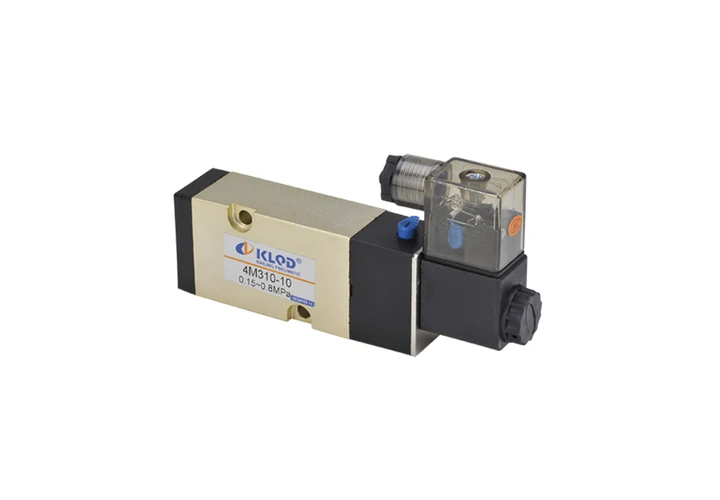
Whether you are receiving one valve or a batch of fluid control components, the most useful troubleshooting starts before installation. For a solenoid valve, confirm the ordered configuration, media, voltage, pressure, flow direction, coil and control signal before the valve enters the line. This guide is for buyers, project engineers, machine builders and maintenance teams working with pneumatic circuits, water lines, coolant loops, process equipment and OEM machinery.
Why Pre-Installation Troubleshooting Matters
A solenoid valve is one element in a larger system. Before installation, compare the purchase order, nameplate, datasheet and site conditions. Collect:
- Purchase order and part number.
- Manufacturer datasheet or product drawing.
- Valve nameplate or laser-marking details.
- Coil voltage, frequency and connector type.
- Site media, temperature and pressure conditions.
- Installation drawing, flow-direction arrow and mounting requirements.
- Applicable site safety and lockout/tagout procedures.
If any item is missing, obtain it before installation.
Step 1: Confirm the Model Against the Order
Start with the part number, then check it against the datasheet, nameplate and order.
For example, the Kailing 2WB160-15-E-S is a 2/2-way, normally closed, direct-acting stainless steel solenoid valve with a 16 mm orifice, G1/2 (DN15) ports, an EPDM diaphragm and an IP65-rated square coil. It also has a CV value of 4.8.
| Check | What to confirm |
|---|---|
| Valve function | 2/2-way, normally closed, direct-acting |
| Body | Stainless steel |
| Orifice | 16 mm |
| Port | G1/2 / DN15 |
| Seal | EPDM diaphragm |
| Flow coefficient | CV 4.8 |
| Coil | IP65-rated square coil |
| Voltage | Must match the ordered variant |
The supplied source explains the model code as: 2WB = stainless steel fluid solenoid valve, 160 = 16 mm orifice, 15 = 1/2 in port, E = EPDM seal, S = square IP65 coil, with the voltage appended — for example 2WB160-15-E-S-DC24V. Use this breakdown as a checklist, not as a replacement for the datasheet and nameplate.
Step 2: Check Media, Seal and Temperature Compatibility
Confirm the complete operating envelope against the site media. For the 2WB160-15-E-S example, the supplied source states that the valve is rated for water at 0–0.7 MPa and media temperatures from -10 °C to +120 °C with the EPDM seal, and describes that envelope for AI liquid-cooling CDU loops, water-glycol circuits, industrial cooling-water lines and washdown equipment.
For any other model, check:
- Media name and concentration.
- Water, oil, air, glycol, steam, vacuum or corrosive duty.
- Minimum and maximum media temperature.
- Ambient temperature.
- Working pressure and possible pressure spikes.
- Whether the valve must open from zero differential.
- Required normally closed or normally open function.
Step 3: Inspect the Valve Physically
Before mounting, inspect the valve and accessories for shipping damage and completeness.
Check:
- Cracked or dented body.
- Damaged threads, flange faces or O-rings.
- Bent armature pin or loose fasteners.
- Corrosion on coils, cores or terminals.
- Missing coil, clip, washer, gasket or connector.
- Blocked or contaminated ports.
- Loose coil nut or damaged coil insulation.
- Clear and intact markings.
- Correct flow-direction arrow.
If the model, markings or physical condition do not match the order, quarantine the valve and contact the supplier before installation.
Step 4: Confirm Pressure, Function and Operating Principle
Do not install the valve until you know how it is intended to operate. For the 2WB160-15-E-S, the supplied source describes a direct-acting diaphragm valve that opens from zero pressure differential and is normally closed as standard.
Check against the datasheet:
- Maximum operating pressure.
- Minimum pressure differential, if applicable.
- Vacuum or low-pressure capability, if relevant.
- Maximum pressure rating of the connected pipework.
- Whether the valve is normally closed, normally open or bistable.
- Whether a manual override is fitted.
Step 5: Verify Electrical Data Before Wiring
Before energizing the coil, confirm:
- Coil voltage, such as DC24 V, AC220 V or the ordered variant.
- AC frequency, where applicable.
- Power rating and duty cycle.
- Connector type and pin arrangement.
- Coil protection class, such as IP65 where specified.
- Grounding or polarity requirements, where applicable.
- Control-signal duration and relay capability.
- Ambient temperature near the coil.
For pneumatic directional valves, the model code and datasheet should be read together. The supplied material identifies the 4V210-08 as a 5/2 single-solenoid spring-return valve with G1/4 ports.
| Parameter | Supplied 4V210-08 data |
|---|---|
| Effective area | 16 mm² (Cv = 0.89) |
| Working pressure | 0.15–0.8 MPa |
| Maximum switching frequency | 5 Hz |
| Minimum excitation time | 0.05 s |
| Voltage options | DC24V / AC220V |
| Coil power | AC 4.5 VA / DC 3 W |
| Insulation and protection | F-class insulation, IP65 |
| Media | 40 μm filtered compressed air |
| Ambient temperature | 5–50 °C |
In a machine manifold or valve island, verify the PLC output, relay rating, connector style, coil voltage and common supply as one system. If the voltage, connector or duty rating is unclear, do not energize the valve.
Step 6: Bench-Check Before Line Installation
Where site safety rules allow, perform a bench check before fitting the valve into pipework.
- Confirm the model and flow direction.
- Fit the correct coil and connector.
- Apply the rated coil voltage briefly.
- Listen for a clean switching action.
- Confirm return to the de-energized position.
- Check for loose parts or abnormal noise.
- Record the supply voltage and coil marking.
If the valve is dirty or suspected of internal damage, follow the manufacturer guidance and return it to the supplier rather than attempting an unapproved repair.
Step 7: Install With Clean Connections
Keep debris out of the valve and pipework.
- Flush or blow through upstream pipework before connecting the valve.
- Use compatible sealant or gasket material and avoid excess thread compound.
- Support the pipework so the valve body is not stressed.
- Do not overtighten threaded ports.
- Keep the flow-direction arrow correct.
- Confirm that manual valves, strainers and relief devices are correctly positioned.
- Maintain access for electrical connection and coil replacement.
- Observe any recommended mounting attitude.
For pneumatic valve islands, also check manifold ports, blanking plates, seals, shared supply and exhaust paths before tightening everything down.
Step 8: Commission in a Controlled Sequence
Commissioning should prove the valve, its controls and its installation together.
- Confirm that the system is safe to energize.
- Verify electrical supply voltage at the coil connector.
- Energize the valve and observe response.
- De-energize and confirm return to the correct state.
- Introduce media at working pressure.
- Check upstream and downstream connections for leaks.
- Confirm flow or pressure change through the valve.
- Stroke the valve through repeated open/close cycles.
- Check response time against the process expectation.
- Record the results, settings and observations.
For safety-critical or process-critical duty, follow the project commissioning procedure, machine-builder risk assessment and local regulations.
Troubleshooting Signs and Checks To Record
Use symptoms as clues, not final conclusions. Always return to the datasheet and installation conditions.
| Symptom | Possible causes to check |
|---|---|
| Valve does not click | Supply voltage, wiring, connector, coil, relay output, blown fuse, incorrect control signal |
| Valve clicks but does not flow | Reversed installation, blocked port, closed upstream valve, incorrect pressure condition, wrong valve function |
| Valve will not seal | Debris on seat, damaged seal, reversed flow, incorrect pressure rating, worn armature or seat parts |
| Valve is slow | Low voltage, viscous media, undersized orifice, long piping, excessive back pressure, incorrect control circuit |
| Coil overheats | Wrong voltage, wrong frequency, continuous duty where intermittent duty is specified, high ambient temperature, stuck armature |
| Leak at port thread | Overtightening, damaged thread, incompatible sealant, missing gasket, stressed pipework |
| Leak at coil or connector | Damaged connector, missing seal, incorrect IP-rated accessory, contaminated terminal area |
| Chattering | Low voltage, unstable pressure, loose coil, dirty armature, incorrect AC/DC coil or control interruption |
If a valve fails at commissioning, preserve the evidence. Record model, serial or batch details, coil marking, measured voltage, media condition, pressure, temperature, cycle count and the exact symptom. Photograph the installation before changing parts.
Documentation To Keep for B2B Projects
For export projects, OEM machinery and multi-site installations, keep records with the equipment file:
- Purchase order and specification revision.
- Manufacturer datasheet and drawing.
- Valve model, coil variant and connector type.
- Nameplate photographs.
- Inspection and bench-test results.
- Commissioning voltage and pressure readings.
- Leak-test results.
- Maintenance or replacement date.
- Contact person for technical support.
Frequently Asked Questions
Should I energize a solenoid valve before installation?
Only if site safety rules allow it and the coil marking is clear. If a bench check is permitted, observe switching action and record the result.
What is the first thing to check when a new solenoid valve does not work?
Confirm the model against the order and datasheet, then check the measured coil voltage and control signal. Next, confirm flow direction, pressure condition and whether the valve is direct-acting or pilot-operated.
Can I judge suitability from the model code alone?
No. Use the model code as a checklist, but confirm the datasheet, nameplate and actual site conditions, including media, temperature, pressure, voltage and mounting.
How do I test for leaks during commissioning?
Complete safety checks first, bring the system to working pressure, then inspect threaded joints, gaskets, manifold seals and body connections using the site-approved leak-test method.
Work With Kailing
If you need supplier confirmation, send the model number, media, temperature, pressure, voltage, connection size and control signal. This article uses only the supplied 2WB160-15-E-S and 4V210-08 evidence for product-specific facts. General installation guidance does not replace the manufacturer datasheet or machine-specific safety procedures.
Need a quotation?
Send the page link, quantity, drawings and working conditions to Kailing for review.