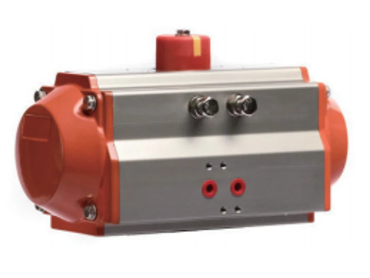
AT-SR is the single-acting spring-return option in the AT pneumatic actuator family for quarter-turn valves. Compressed air powers one stroke, and springs power the return stroke when actuator air is exhausted. Select the configuration using both air-stroke and spring-stroke torque throughout travel, together with the actual valve data and available air supply. The required valve return position depends on the assembled valve orientation and pilot circuit.
AT-50S - Product family: AT-SR Spring Return Pneumatic Actuator
- AT-50S
- AT-63S
- AT-75S
- AT-100S
- AT-125S
- AT-160S
- Model
- Valve type
- Fail position
- Valve torque
- Safety factor
- Air pressure
- Spring set
- Quantity
English catalog reference and page numbers
This page references the English AT actuator catalog available below. Printed pages 62-67 are pages 1-6 of this PDF; the filename uses English master-PDF physical pages 65-70. Spring-return torque is on printed page 63, materials on page 64 and mounting/dimension references on page 67. Confirm current configuration-specific data before ordering.
What to confirm for an AT-SR quotation
Provide valve type and model, valve torque data and its source, required operating and return positions, minimum and maximum air pressure at the actuator, and proposed actuator model and spring quantity. Include mounting drawings, drive connection dimensions, temperature and environment, cycle frequency and quantity. Confirm whether the scope includes the bracket, coupling, pilot valve, position feedback, air-preparation components and assembly checks. State required inspection records, approvals, delivery date and documentation for confirmation.
Return position and pilot circuit
Specify loss-of-air, loss-of-power and loss-of-signal requirements separately. Spring return requires the actuator air to be exhausted; pilot-valve state, air path, controls and assembled valve orientation determine the result. Confirm the complete assembly behavior for the application. A component catalog alone does not demonstrate a validated shutdown function.
Current drawings and model configuration
The English installation page is an AT-series reference. Confirm the exact model, spring arrangement, flange, drive, coupling and installation envelope. Do not transfer AT115 dimensions to AT125S or use a catalog example as a complete selection for another configuration. Existing model aliases identify the product family; confirm the available configuration, drawings and supply scope before ordering.
| Parameter | Value |
|---|---|
| Action | Single acting, spring return |
| Nominal rotation | 90 degrees |
| Travel adjustment | Independent open/closed position adjustment; the English catalog lists +/-5 degree adjustment. Confirm the setting range for the selected configuration. |
| Operating pressure reference | English catalog reference for single acting: 4.5-8 bar. Confirm the selected model and spring quantity against the minimum and maximum air pressure available at the actuator. |
| Maximum working pressure reference | 10 bar in the English catalog. This maximum is not the sizing pressure or a guarantee of every valve-and-accessory assembly rating. |
| Standard temperature reference | -20C to +80C in the English catalog. Confirm the selected seal and actuator configuration. |
| Optional temperature references | -35C to +80C or -20C to +150C in the English catalog. Confirm the available configuration and matching seals. These are actuator references, not valve media-temperature ratings. |
| Spring material reference | High-alloy spring steel with epoxy resin coating, as listed in the English catalog. |
| Seal references | NBR (NBR70) listed as standard; Viton or silicone rubber listed as options. Confirm the supplied seal specification. |
| Return behavior | Springs drive the return stroke when actuator air is exhausted. Specify the valve return position and verify loss-of-air, loss-of-power and loss-of-signal behavior with the complete pilot circuit. |
| Top accessory interface reference | VDI/VDE 3845 / NAMUR reference for position switches and positioners. Confirm accessory dimensions and supply scope. |
| Side pilot-valve interface reference | VDI/VDE 3845 / NAMUR reference. Confirm pilot-valve interface, voltage, circuit and environmental requirements. |
| Valve interface reference | ISO 5211 / DIN 3337 references in the catalog. Verify flange, drive connection, bracket and coupling dimensions against current drawings. |
| Sizing confirmation | Check air-stroke and spring-stroke torque over the required travel with actual valve duty, available pressure and agreed sizing margin. |
| Duty confirmation | State expected cycle frequency, load, environment and maintenance requirements for quotation. |
Spring-return torque examples from the English AT catalog
| Model | Spring quantity | Air stroke at 5 bar, 0 degree start / 90 degree end (N.m) | Air stroke at 5.5 bar, 0 degree start / 90 degree end (N.m) | Spring stroke, 90 degree start / 0 degree end (N.m) |
|---|---|---|---|---|
| AT-50S | 6 | 12.2 / 9.4 | 13.9 / 11.1 | 7.2 / 4.4 |
| AT-50S | 10 | 9.2 / 4.6 | 10.9 / 6.3 | 12 / 7.4 |
| AT-63S | 6 | 21.5 / 16.6 | 24.4 / 19.5 | 12.7 / 7.8 |
English catalog printed page 63 (PDF page 2; master-PDF physical page 66). Reference rows for the stated spring quantities and pressures, not valve-sizing recommendations. Confirm current actuator configuration, valve torque throughout travel, minimum/maximum air pressure and the agreed sizing margin. A dash in the source table is not a zero-torque rating.
English AT catalog download reference
| Reference | Printed page | Page in this PDF | Confirm before ordering |
|---|---|---|---|
| Single-acting technical references | 62 | 1 | Selected model, seals, spring quantity and available air pressure |
| Spring-return torque table | 63 | 2 | Both strokes, start/end outputs and applicable pressure column |
| Materials and options | 64 | 3 | Supplied seals, materials and actuator environment |
| Mounting and dimensions | 67 | 6 | Current model-specific drawings and valve interfaces |
The public download contains printed pages 62-67. Its filename refers to physical pages 65-70 in the English master PDF. These references do not establish equivalence to a different catalog version.
Frequently Asked Questions
- FAQ Where are the torque and mounting references?
The linked English AT actuator catalog contains spring-return torque on printed page 63 (PDF page 2) and mounting/dimension references on printed page 67 (PDF page 6). Request current model-specific drawings and torque data for final selection. - FAQ Will it return the valve when power is lost?
Spring return requires actuator air to be exhausted. Power or signal loss behavior depends on the pilot valve, complete circuit and assembled valve orientation. Specify the required return position and have the assembly behavior confirmed. - FAQ Is a product name enough for a quotation?
A product name can identify the family. Final configuration and quotation require valve torque data, available air pressure, spring quantity, mounting dimensions, operating conditions, accessory scope and quantity. - FAQ Can these torque examples size my existing valve?
These reference rows apply to the stated spring quantities and pressures. Compare the full air-stroke and spring-stroke output with valve torque throughout travel and actual supply conditions. Confirm the sizing margin and mechanical interfaces for the complete assembly.
Need a quotation?
Send the model, medium, pressure, port size, body material and quantity for review.