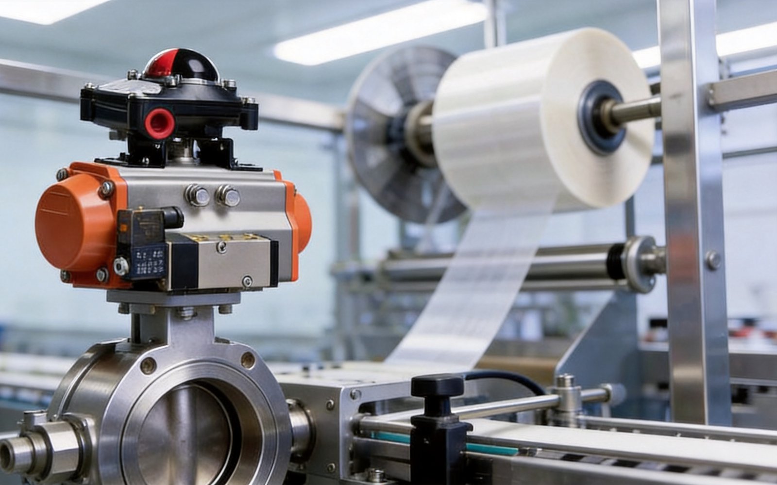
To retrofit a manual ball or butterfly valve with an AT-SR spring-return pneumatic actuator, first collect the existing valve's torque data, mounting drawing and operating conditions. Check the proposed actuator and spring configuration against the minimum air pressure available at the actuator. Define the required return position and review the pilot circuit, mounting parts and supply scope together. A spring-return actuator alone does not establish a validated shutdown function for the complete assembly.
Establish whether the existing valve can be retained
Start with the valve nameplate, manufacturer and model, valve type, size and connection. Include the process medium, normal and maximum pressure and temperature, operating frequency, and any problems with the existing valve. Ask the valve supplier for torque data through the required travel under those conditions; a handwheel size or pipe DN is not an actuator-sizing basis.
Provide photos of the valve with the manual operator, its mounting area and stem, plus a dimensioned drawing if available. State whether you want the existing valve body retained, an actuator supplied separately, or a complete replacement valve package. Retaining the valve is a project decision after its condition, duty and interfaces have been reviewed, not an automatic benefit of adding an actuator.
Use the AT-SR spring-return product page to identify the actuator family. If the desired action is still being decided, compare the AT-DA double-acting reference and the double-acting versus spring-return guide. The retrofit checklist below concentrates on the existing valve and its installation interfaces.
Check torque using the actual air pressure and spring set
Read the English AT actuator catalog excerpt together with the proposed model code. Keep the valve torque requirement, actuator output and installation conditions in the same review package.
Provide the minimum and maximum air pressure measured at the actuator, including the supply condition during operation. For a spring-return selection, compare both the air stroke and the spring stroke through the required travel, including their start and end values. Confirm the spring configuration, direction and selection margin with the engineer responsible for the assembly; do not select from one headline torque value.
The following examples come from the torque table on printed page 63 (PDF page 2) of the linked English excerpt. They illustrate why the pressure column and spring set must be identified. They are reference rows, not recommendations for a particular valve size or process. The excerpt's printed pages are 62–67; its filename is not a printed-page reference.
| Catalog model | Spring count | Air torque at 5 bar, 0° start / 90° end (N·m) | Spring torque, 90° start / 0° end (N·m) |
|---|---|---|---|
| AT-50S | 6 | 12.2 / 9.4 | 7.2 / 4.4 |
| AT-50S | 10 | 9.2 / 4.6 | 12 / 7.4 |
| AT-63S | 6 | 21.5 / 16.6 | 12.7 / 7.8 |
Use the full model table for other spring sets or supply pressures. Ask for confirmation when a webpage summary, a catalog example and the direct model table differ. If the valve torque curve or actual minimum air pressure is unknown, record it as an unresolved sizing input. Do not turn these examples into a DN-to-actuator shortcut or transfer them to a different configuration.
Specify the required return behavior for the complete circuit
State the process position required after each failure condition. Have the valve orientation, actuator assembly, pilot valve and control circuit checked together against those requirements.
| Condition to review | Requirement to state | Configuration to check |
|---|---|---|
| Loss of air supply | Required valve position and any project-specific action requirements | Spring arrangement, return direction, valve torque and the air path needed for return |
| Loss of electrical power | Required valve position | Pilot valve's de-energized state and the complete pneumatic/electrical circuit |
| Loss of control signal | Required valve position or other defined behavior | Controller, pilot/positioner response and how the circuit handles that signal loss |
Do not treat “loss of air,” “loss of power” and “loss of signal” as the same event. Spring-return capability does not by itself demonstrate the behavior of every connected pilot circuit. The plant or machine team must define the required state; this guide does not prescribe fail-open or fail-closed positions for particular process lines.
For an oil-and-gas or hazardous-area project, list the actual environmental and documentation requirements for the actuator and every accessory. Request evidence for the quoted configuration and agreed assembly checks. A general actuator page or a component cycle-life figure is not proof of emergency-shutdown performance, hazardous-area approval or the service life of the retrofit installation.
Resolve the mechanical interfaces before ordering
Use the catalog drawings and the existing valve drawing together. A matching mounting-standard label does not resolve every flange, stem or coupling dimension.
| Interface or condition | Information to provide | Written confirmation to request |
|---|---|---|
| Valve mounting pad | Flange pattern, hole positions and drawing revision | Match to the proposed actuator mounting pattern |
| Valve stem and drive | Shape, dimensions, height, orientation and photos | Coupling geometry, engagement and assembly direction |
| Bracket and coupling | Existing parts or required new parts; installation drawing | Included items, dimensions and responsibility for the interface |
| Travel and working space | Required rotation, open/closed direction, obstructions and access | Travel settings, package envelope and maintenance access |
| Ambient environment | Temperature, exposure, washdown and other site requirements | Applicable actuator/accessory limits and documents |
Keep actuator ambient conditions separate from the process fluid inside the valve. The actuator's seal or temperature option does not establish the valve's wetted-material compatibility. If the old valve lacks a suitable mounting pad, submit its drawings for review before assuming a bracket can make the retrofit work.
List the parts included in the quotation
Identify each item in the package and whether it is supplied, retained from the existing installation or to be sourced separately.
| Item | Detail to agree before quotation |
|---|---|
| Actuator | Complete model code, spring arrangement, return direction and applicable torque data |
| Pilot valve | Air-control function, mounting/connection, supply voltage and connector; circuit behavior under the defined failures |
| Position indication or control | Required position feedback, signal and wiring; identify a positioner separately if controlled positioning is required |
| Mounting parts | Bracket, coupling, fasteners and installation drawing |
| Air connections | Required fittings, tubing and air-preparation scope; confirm what is included |
| Documents and checks | Model-specific documents, drawing revisions and agreed functional checks |
The actuator-accessories guide helps identify accessory functions. For a complete new valve-and-actuator package, use the ball and butterfly valve package checklist. Neither guide confirms that all listed accessories are included with an actuator-only quotation.
Send a traceable retrofit request
Send the nameplate and installation photos, valve torque source, process conditions, air-supply range, interface drawings, required failure behavior, parts list, quantity, requested documents and target date through the existing contact page. Mark missing inputs for confirmation rather than guessing them.
Ask the quotation to identify the final actuator and spring configuration, retained valve, mounting drawing, included accessories and proposed checks under the agreed conditions. Confirm availability, sample terms, required documentation and lead time for the actual scope. Keep the accepted drawing revision and model codes with the order so later substitutions or repeat orders can be reviewed against the same configuration.
Frequently Asked Questions
- FAQ Can the existing manual valve always be retained?
No. Confirm its condition, operating duty, torque data and mounting interfaces before deciding to retain it. Provide the nameplate, drawings and installation photos. - FAQ Can I choose an AT-SR model from the valve DN alone?
No. Provide valve torque through travel, actual minimum supply pressure, spring configuration, return direction and interface details for a complete sizing review. - FAQ Does spring return guarantee the valve position after power loss?
The complete circuit must be reviewed. State the required position after air, power and signal loss separately, then check the pilot valve, air path, controls and assembly configuration. - FAQ Can the 5-bar reference row be used at a different air pressure?
Use the applicable pressure column and spring set in the full model table. Do not substitute a 5-bar reference row for output data at another supply condition. - FAQ Are the bracket, coupling and pilot valve included?
Ask the quotation to identify each supplied, retained or separately sourced item. An actuator model name alone does not establish the complete retrofit supply scope.
Need a quotation?
Send the page link, quantity, drawings and working conditions to Kailing for review.