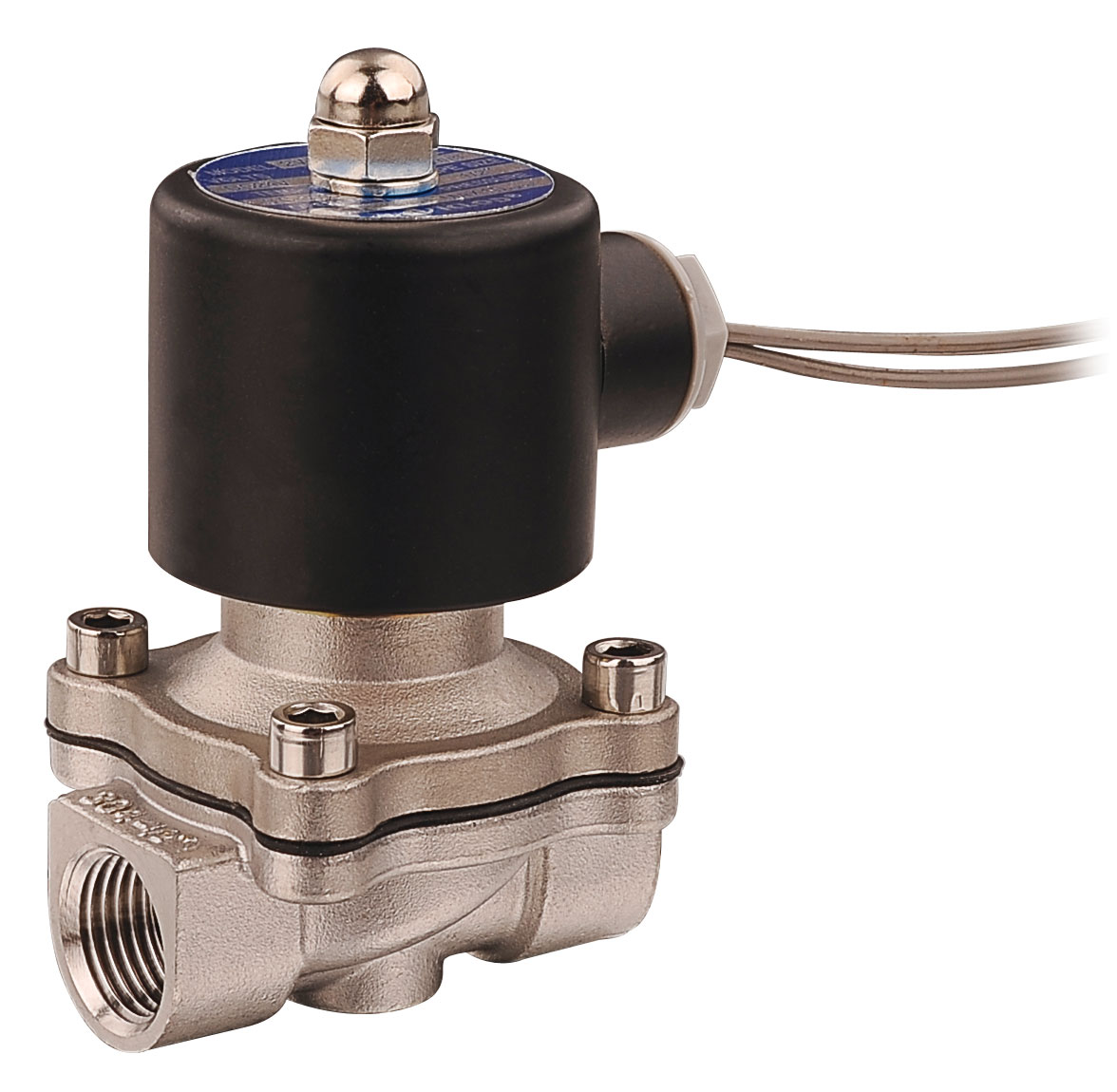
Sizing a directional control valve is a flow-matching exercise, not a thread-matching exercise. The valve must pass enough air to move the cylinder at the required speed and change state fast enough for the cycle — a G1/2 port on a valve with a small effective orifice can still starve the actuator.
This guide walks through the four checks a buyer or project engineer should complete before ordering: cylinder air demand, valve flow capacity, port and fitting sizing, and response behavior. The examples use Kailing directional and fluid solenoid valves, but the method applies to any pneumatic circuit.
Why flow matching matters
A directional valve is the bottleneck of the actuation circuit. If its effective orifice or Cv is too small for the cylinder's air demand, the cylinder moves slower than the machine cycle requires, and pressure drop across the valve wastes compressor energy. If the valve is grossly oversized, you pay for capacity you never use and the flow becomes harder to meter precisely.
The reverse mistake is equally common: two valves with the same G1/4 port can have very different flow capacities depending on their internal orifice and spool design. Port thread alone tells you nothing about throughput — always read the rated flow data.
Step 1: Calculate the cylinder's air demand
Start from the actuator side, not the valve catalog:
- Cylinder bore and rod area. For a double-acting cylinder, the extend stroke uses the full piston area; the retract stroke uses the annular area (piston area minus rod area). The retract side usually needs less air but must still exhaust through the valve.
- Required speed. Divide stroke length by the target cycle time to get piston speed.
- Air consumption per stroke. A practical first-pass formula: air volume consumed = piston area × stroke × number of cycles, converted to free air at the working pressure. At 0.6 MPa gauge, compressed air roughly expands to 7 times its free-air volume, so a cylinder that sweeps 0.5 L of volume consumes about 3.5 L of free air per double stroke at that pressure — the exact factor depends on your absolute pressure.
- Peak demand per port. Divide by the valve's opening time and the acceptable pressure drop. This peak flow, expressed in L/min (ANR) or SCFM, is what the valve must pass.
For fluid actuators (hydraulic-style duty, coolant or water cylinders), the same logic applies with liquid flow in L/min instead of free air.
Step 2: Read the valve's flow capacity correctly
Valve catalogs express capacity in one or more of three ways: Cv/Kv coefficient, effective orifice area (mm²), and nominal port size. Cv is the comparable figure across brands; the effective orifice in mm² is common on Asian-market pneumatic valves. When comparing suppliers, convert to a single unit.
As a reference point, the Kailing 4M310-08 — a 5/2-way single-solenoid NAMUR valve for quarter-turn actuators — has an effective orifice of 25 mm² (Cv 1.4) and works at 0.15–0.8 MPa (21–114 psi). That capacity suits a mid-size rack-and-pinion actuator cycling a ball or butterfly valve; a large gate valve with a high-torque actuator will need the next body size up.
For liquid duty the same discipline applies. The 2WB160-15-E-S stainless steel solenoid valve is rated CV 4.8 with a 16 mm orifice and a G1/2 (DN15) port, sized for cooling-water and coolant lines. On flanged lines, capacity scales with the body size: the 2WBF15 offers CV 4.8, rated for air 0–1.0 MPa and water 0–0.7 MPa, while larger 2WBF bodies step up to CV 7.6, 12 and beyond. Confirm the Cv against your line's required flow, not the flange size.
| Reference model | Function | Flow indicator | Working pressure | Typical duty |
|---|---|---|---|---|
| 4M310-08 | 5/2, single solenoid, NAMUR | 25 mm² / Cv 1.4 | 0.15–0.8 MPa | Quarter-turn actuator control |
| 2WB160-15-E-S | 2/2 direct-acting diaphragm | Cv 4.8, 16 mm orifice | Water 0–0.7 MPa | Cooling water, coolant, glycol |
| 2WBF15 | 2/2 flanged diaphragm | Cv 4.8 | Air 0–1.0 MPa; water 0–0.7 MPa | Flanged fluid lines |
| QX23-08 / QX23-10 | 3/2 direct-acting | 1/4 in and 3/8 in sizes | 0–0.9 MPa | Vacuum packaging, zero-differential circuits |
The QX23 series shows the three-way case: two catalog sizes, QX23-08 (1/4 in) and QX23-10 (3/8 in), cover 0–0.9 MPa with AC 10 W / DC 13 W coils and five voltage references. Three-way valves must pass air in both directions — supply and exhaust — so check the exhaust path capacity too when the actuator must retract quickly.

Step 3: Size ports and fittings for the whole path
The valve is one restriction in a chain that includes fittings, tubing and the cylinder ports. Rules of thumb:
- Keep the valve port at or above the cylinder port size. Stepping down at the valve throttles the whole circuit.
- Count the fittings: each quick coupling and elbow adds restriction. A long small-bore tube run can undo a correctly sized valve.
- On NAMUR interfaces, the valve's mounting face replaces piping — verify the interface standard and port drilling instead of thread adapters.
- For high-cycle circuits, favor shorter runs and larger tube ID on the exhaust side; exhaust restriction is the usual cause of slow retraction.
If the supplier offers both NPT and G (BSP) threads, confirm which standard your manifold and fittings use before ordering — mixing standards at G1/2 and DN15 sizes is a frequent cause of leaks and rework on export projects.
Step 4: Verify response and switching behavior
Flow capacity sets the maximum speed; switching behavior sets whether the machine can actually use it. Three checks:
- Switching frequency. The 4M310-08, for example, is rated for a maximum switching frequency of 4 cycles per second. If your cycle demands faster commutation, you need a valve with a higher rated frequency or a shorter stroke cylinder.
- Pilot type and minimum pressure. Internally piloted valves need a minimum pressure differential to shift reliably; direct-acting valves open from zero differential. Vacuum circuits and low-pressure lines require direct-acting designs like the QX23.
- Fail-safe position. Single-solenoid spring-return valves return to a defined state on power loss; double-solenoid valves hold position. Match this to the machine's safety logic, not just the cycle diagram.
Response also degrades with long control lines and undersized pilot supply. On distributed circuits, place the valve close to the actuator and run electrical control lines instead of long air lines.
Common mismatch scenarios
- Cylinder crawls on retract. The exhaust path through the valve or muffler is undersized; check annular-side flow and exhaust fittings.
- Valve buzzes or fails to shift at low pressure. An internally piloted valve is running below its minimum pilot pressure; switch to a direct-acting model.
- Flow is correct but slow. The restriction is in tubing, couplings or cylinder ports, not the valve — audit the full path.
- Two quotes with the same port but different prices. Compare Cv, orifice area and coil power; the cheaper valve may pass half the air.
FAQ
Should I size a directional valve by port size or by Cv? By Cv (or effective orifice), always. Port size defines the connection, not the throughput. Two valves with the same G1/4 port can differ substantially in rated flow; the Cv figure is the comparable spec across brands.
How much spare flow capacity should I leave? A common engineering margin is 20–30% above calculated demand to cover pressure drop in fittings, filter loading and future speed increases. Gross oversizing beyond that makes metering harder and raises coil power cost on solenoid types.
Does a bigger valve make the cylinder respond faster? Only up to the point where the valve is no longer the bottleneck. Once valve Cv exceeds what the cylinder ports and tubing can pass, further upsizing adds cost without speed. Audit the full flow path before upsizing.
What data should I send for a flow-matching quote? Cylinder bore, rod diameter, stroke, required cycle time, working and minimum pressure, media, ambient conditions, coil voltage and connection standard. With these, the manufacturer can propose a valve whose Cv, pressure band and response match the duty instead of guessing from a port size.
Get a flow-matched valve proposal
If you are selecting directional valves for cylinders, actuators or fluid lines, send the cylinder and circuit data listed above to the Kailing team via the contact page. You can also browse the pneumatic valve range and the DNC-type ISO 15552 cylinder guide to prepare your RFQ — the factory engineering team will confirm Cv, port and voltage selection against your duty cycle before quoting.
Need a quotation?
Send the page link, quantity, drawings and working conditions to Kailing for review.