
A pneumatic actuator accessory BOM should identify the air-control valve, required position feedback or modulating control, mounting parts and air connections. For each item, record the function, electrical and pneumatic requirements, interface drawing and scope of supply. A list of model names alone does not confirm that the parts fit or that a complete assembly is included.
Start with the control task
State whether the valve needs open-close operation or movement to intermediate positions. Then specify what the control system must receive: an open/closed indication, a position signal or another defined response. Position feedback and position control are separate requirements; a limit switch box and a positioner should not be treated as interchangeable accessories.
Record the selected actuator model, action type and available air pressure. Review the required behavior after loss of air, electrical power and control signal separately. A spring-return actuator name does not establish the behavior of the complete valve, pilot valve, air circuit and controls. Use the double-acting and spring-return comparison for that selection question, then use the BOM below to identify the accessories needed for the chosen arrangement.
Build a component-by-component BOM
Use one line for each item and quantity. Mark unconfirmed information as to be confirmed, rather than assuming a standard configuration. The reference pages below help identify candidate components; they do not establish compatibility with every actuator.
| BOM item | Function to define | Information to provide | Scope to confirm in the quotation |
|---|---|---|---|
| Air-control valve and coil | Route actuator air for the selected action | Circuit function, ports, supply pressure, coil supply and connector, manual-override requirement | Complete valve or replacement coil; pipe-connected or direct-mounted arrangement |
| Limit switch box | Provide the required end-position feedback | Required circuit/switch type, electrical ratings, wiring, cable entry and mounting drawing | Box configuration, bracket, coupling, cable gland and wiring responsibility |
| Positioner, if required | Control intermediate valve position | Input signal, required feedback, actuator action, air supply and mounting details | Exact positioner variant, mounting kit, setup and acceptance requirements |
| Bracket, coupling and fasteners | Connect the valve, actuator and accessories | Valve top-flange drawing, shaft shape and dimensions, actuator/accessory interface drawings | Each part, quantity and the party responsible for dimensional matching |
| Air preparation and connections | Provide the specified air condition and route the air | Site air condition, pressure at the package, connection sizes, tubing layout and space limits | Filter/regulator arrangement, fittings, tubing and installation responsibility |
| Assembly and checks | Define what arrives ready for installation | Assembly drawing, agreed operating sequence, feedback and inspection requirements | Loose components or assembled package; which setup and checks are included |
Separate an air-control valve from its replacement coil
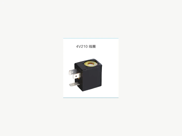
The 4V directional-valve family is a reference for pneumatic control-valve options. Identify the required circuit and the complete valve configuration before selecting its coil or connector. The existing 4V210 coil reference concerns a replacement coil; ordering a coil does not order the complete directional valve.
For a pipe-connected arrangement, provide the intended air-port connections, tubing and fittings. For direct mounting, obtain the mating interface drawings for both the actuator and valve. A catalog mention of a mounting standard does not prove that a particular valve, bracket and actuator combination fits. Confirm the exact variant and physical clearance before ordering.
Match feedback and modulating requirements separately
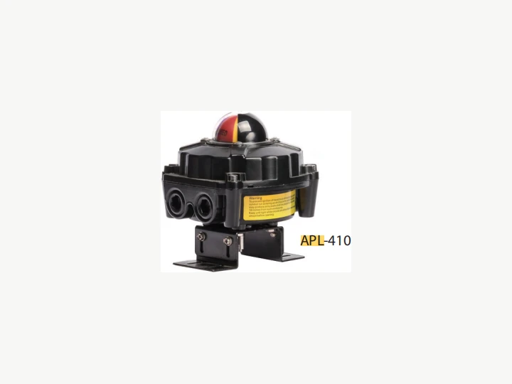
The APL-210 and APL-410 pages identify position-feedback-box candidates. Choose using the required feedback circuit, mounting dimensions, cable connection and site conditions. A family or model name alone does not confirm switch ratings, enclosure protection or suitability for a hazardous location. Request the applicable configuration details and documents when those requirements matter.
Use the YT-1000 positioner reference when reviewing a modulating-control requirement. Confirm the exact input signal, actuator action, feedback arrangement and mounting kit for the selected variant. Do not infer a signal range or universal AT-series compatibility from the product name. A passive switch contact should also not be assigned a power-supply requirement by copying the pilot-valve coil voltage; review each electrical circuit on its own terms.
Provide the interfaces and supply responsibilities
For the actuator itself, refer to AT-DA or AT-SR as appropriate. Provide the exact model and configuration already selected for the valve duty. Keep actuator sizing and valve suitability separate from accessory selection; the manual-valve retrofit checklist covers the retained-valve and mounting review.
Send clear photos where an existing assembly is retained, but include dimensioned drawings for the mating parts. Identify rotation, mounting orientation, available space and access for cables or manual operation. Ask the supplier to flag any unresolved interface before confirming the accessory BOM.
| Purchase-pack field | Buyer supplies | Supplier confirms |
|---|---|---|
| Valve and actuator | Exact models, duty, configuration and drawings | Applicable actuator reference and unresolved sizing/interface questions |
| Control and feedback | Open-close or modulating task, signal and wiring requirements | Proposed valve, switch or positioner variant and connection details |
| Utilities and environment | Available air, electrical supply, temperature and any special site requirements | Required configuration and supporting documents for that environment |
| Mechanical package | Valve shaft/top-flange and actuator/accessory drawings | Matched brackets, couplings, fasteners and any excluded parts |
| Supply and acceptance | Quantities, installation responsibilities and required checks | Itemized supplied/excluded scope, assembly/setup responsibilities and agreed checks |
This is a procurement worksheet, not an example of a verified customer installation. Leave unknown fields open for review. Do not assume assembly, calibration, testing, certification or a delivery date is included simply because the quotation lists several accessories.
Request an itemized accessory quotation
Prepare the BOM, control requirements and interface pack before using the existing quotation entrance. Ask for an itemized response showing the selected variant, quantity, included mounting/connection parts, exclusions and remaining questions. For a complete valve-and-actuator purchase, continue with the ball/butterfly valve package RFQ guide instead of treating this accessory checklist as a complete package specification.
| Parameter | Value |
|---|---|
| Solenoid valve | Voltage, ports, coil connector and manual override. |
| Limit switch | Feedback type, enclosure and cable entry. |
| Positioner | Control signal and modulating requirement. |
| Mounting | Valve top flange, shaft size and bracket data. |
| Air preparation | Clean and stable compressed air for actuator service life. |
Frequently Asked Questions
- FAQ Does every actuator package need both a limit switch box and a positioner?
No. Define end-position feedback and modulating control separately. Select the accessories for the required control task and review each configuration and mounting interface. - FAQ Is a 4V210 replacement coil a complete air-control valve?
No. A replacement coil is a component. The quotation should identify whether it includes a complete valve, the required valve configuration, coil, connector and mounting or piping parts. - FAQ Are APL-210, APL-410 and YT-1000 directly compatible with every AT actuator?
The linked model pages do not establish universal compatibility. Compare the exact actuator and accessory configuration, mating drawings, electrical or signal requirements and required mounting kit. - FAQ What electrical details should a buyer provide?
Provide the actual coil supply, feedback circuit, required input/output signals and wiring requirements for each item. Do not assume a passive switch contact uses the same supply as a solenoid coil. - FAQ Are assembly, brackets and checks automatically included?
Ask for an itemized supplied and excluded scope. Identify the bracket, coupling, fasteners, connections and responsibility for assembly, setup and agreed checks; model names alone do not establish these services.
Need a quotation?
Send the page link, quantity, drawings and working conditions to Kailing for review.