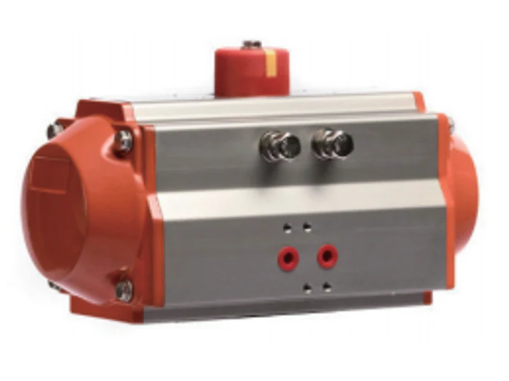
For buyers specifying fluid control components, this guide organizes a preliminary pneumatic actuator torque calculation into a worksheet, a hypothetical example and an evidence checklist. It does not provide a confirmed valve–actuator selection.
Scope: Use this worksheet to prepare a sizing review with the valve and actuator suppliers. Obtain the actual valve torque requirements, actuator output data and an approved calculation method before selection. The numerical example demonstrates arithmetic only; its inputs are not product ratings or recommended sizing margins.
1. Document the valve torque requirements
Request torque records for the actual valve and service conditions. Include the medium, temperature, differential pressure, seat material, operating cycle and anticipated periods without movement. Ask the supplier to identify the conditions and document revision associated with each value.
| Checkpoint | Information to request |
|---|---|
| Opening breakaway | Supplier-defined torque needed to initiate opening |
| Opening travel | Required torque through the opening stroke |
| Closing travel | Required torque through the closing stroke |
| Final seating | Torque needed to reach the specified closed condition |
Opening breakaway, running torque and final seating torque are different selection checkpoints and should not automatically be treated as equal.
Minimum operating torque and maximum allowable stem torque serve different purposes: one addresses the load to be overcome, while the other limits the torque the valve can accept.
Both statements remain pending applicable valve-supplier evidence. Obtain the definitions and limits before applying them. Leave missing values unresolved rather than substituting data from another valve without approval.
2. Obtain approval of the calculation method
The proposed calculation for engineering approval is: required design torque = valve torque × approved sizing factor + additional torque allowance.
This equation is a proposed worksheet, not a validated manufacturer procedure. Ask the responsible engineer to approve the equation, sizing factor, allowance treatment and acceptance criteria. Confirm whether the valve torque already includes margins or additional loads before adding anything further.
No approved factor is supplied. Keep torque inputs in a consistent unit system, document any conversion method and assess opening and closing separately where the approved requirements differ. Do not use the hypothetical factor below as a default.
3. Obtain actuator output at matching conditions
For the air-driven stroke, pneumatic actuator torque depends on the air pressure available at the actuator.
This statement remains pending manufacturer evidence. Request output records for the exact actuator model and configuration at the specified minimum operating pressure. Ask the system designer to identify the pressure condition used for comparison; do not substitute a compressor rating without approval.
At each checked position, available actuator torque must meet or exceed the required design torque.
This is a proposed comparison criterion pending approval of the governing positions and required reserve. Equality at one checkpoint is not presented as assembly acceptance.
For this worksheet, define torque reserve as available actuator torque minus required design torque.
A positive torque reserve establishes only that the stated available torque exceeds the stated design demand at the checked point; it does not approve the assembly.
Record movement direction, travel position, pressure and configuration beside each output value. Obtain a documented method before extrapolating values absent from the applicable output table or curve.
4. Separate configuration-specific assessments
Double-acting actuator
Request opening and closing output records for comparison with the corresponding valve requirements.
Do not assume that a single published maximum torque represents the available output throughout the stroke.
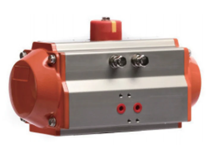
The applicable output profile remains unresolved. Request torque-versus-travel records and identification of the governing positions. Neither selected image establishes a torque curve or performance rating.
Spring-return actuator
For a spring-return actuator, available output must be checked separately for the air-driven stroke and the spring-driven stroke.
Request the exact spring arrangement, movement direction, start and end output for each stroke, and any intermediate values required by the approved assessment procedure.
A successful air-stroke calculation does not establish that the spring stroke can complete the required movement.
Both statements remain pending applicable sizing instructions and configuration-specific records.
Do not describe the assembly as providing a verified fail-safe function merely because a spring-return actuator is selected.
Document the required response to loss of air and other relevant failures. Application-specific verification is missing; no safety function or certification is established here.
5. Calculate a hypothetical example
The following inputs are retained solely to illustrate the proposed equation. They are not supplier data, approved application values or published specifications.
| Example input | Hypothetical value |
|---|---|
| Valve opening breakaway torque | 120 N·m |
| Sizing factor | 1.25 |
| Separate additional torque allowance | 10 N·m |
| Actuator output at the same checkpoint | 175 N·m |
Under these hypothetical inputs, the required opening design torque is 120 × 1.25 + 10 = 160 N·m.
The illustrative torque reserve is 175 − 160 = 15 N·m.
The arithmetic is correct for the stated inputs, but it does not validate the equation or establish an acceptable selection. The factor 1.25 is not recommended, and 175 N·m is not a product rating. No actuator model, pressure or spring configuration is assigned to this example.
Before engineering use, replace every hypothetical input with a traceable, approved value and complete the required direction-, position- and configuration-specific assessments.
6. Review upper torque limits and interfaces
Check the candidate’s maximum transmitted torque under the maximum specified supply condition against the valve supplier’s allowable stem torque.
Also verify the applicable limits of the coupling, bracket and other torque-transmitting parts.
These checks remain pending an approved method and component records. Request drawings and limits covering mounting dimensions, stem engagement, rotation direction and travel. Keep stroke time, control accessories and required failure response as separate review items rather than treating the example calculation as proof that they are satisfied.
7. Close the evidence gaps before selection
Request the current valve torque record and exact actuator output table, including units, pressure, travel positions and configuration. A photograph or a model name does not replace those performance records.
| Unresolved subject | Evidence needed |
|---|---|
| Valve requirements | Service-specific torque records, checkpoint definitions and allowable stem torque |
| Calculation method | Approved equation, factor, allowance treatment and acceptance criteria |
| Actuator output | Exact-model pressure and travel output records with direction and configuration |
| Spring-return assessment | Exact spring arrangement and separate air-stroke and spring-stroke records |
| Upper torque and interfaces | Maximum transmitted torque assessment, component limits and assembly drawings |
| Failure response | Defined scenarios, required response and verification results |
Keep the accepted model code, source document and revision, applicable conditions and review result with the quotation. Use documents that actually apply to the proposed valve-actuator assembly.
Until the necessary records and acceptance criteria are reviewed, describe the result as a preliminary calculation, not a confirmed selection.
Compare the existing AT double-acting and AT spring-return references. The manual-valve conversion checklist covers separate mounting and operating requirements.
Frequently Asked Questions
- FAQ Is 1.25 a recommended pneumatic actuator sizing factor?
No. It is a hypothetical input in this draft. No supplied record establishes an approved sizing factor, equation or allowance treatment. - FAQ Does the example establish a suitable actuator model?
No. The example assigns no actuator model, operating pressure or spring configuration. Its results demonstrate arithmetic, not an approved selection. - FAQ Do the selected product images substantiate actuator torque?
No. The supplied image paths and descriptions are not torque-performance records. Applicable output curves and configuration details remain missing.
Need a quotation?
Send the page link, quantity, drawings and working conditions to Kailing for review.